Astronomical Laboratory ASTR:4850,
Fall 2015
by Philip Kaaret
Sections 5.1, 5.8 in Handbook of CCD Astronomy, second edition, by Steve B. Howell.
In this lab, we will do astrometry on images that you obtained using the Van Allen Observatory. We will be looking at a pair of images of the open star cluster M39 obtained in the B-band. You should have one image with the cluster centered in the telescope view of view and another image that is offset by 5 arcminutes in declination. These are the same images from the Aperture Photometry lab. Used the reduced versions of the images that you calculated for that lab. We will also be using a reference image that is a B-band image of M39 from the Second Palomar Observatory Sky Survey (POSS II) downloaded from the STScI Digitized Sky Survey.
Load the POSS2 image of M39 into ds9. As you move the
pointer around on the image, you see the astronomical coordinates
of the pointer position listed in the two boxes next to the
letters WCS or DSS. The astronomical coordinates are
calculated from the pixel position using the so-called 'World
Coordinate System' (WCS) defined in the FITS header of the
image. In ds9, do File/Display Header and then scroll down
until you see the lines describing the FITS header that start with
'WCSAXES'.
WCSAXES gives the number of WCS axes, usually 2 when dealing with
2-dimensional images. WCSNAME gives the name of the WCS
coordinate system. RADESYS gives the particular coordinate
reference system used. We will use using the International
Celestial Reference System (ICRS).
CTYPE1, CTYPE2 specify the projection used for the coordinate
system. The projection is how pixels in the image are mapped
onto the sky. Recall that the celestial sphere is, indeed, a
sphere. Conversely, the surface of a CCD is usually a
plane. For CCD images with relatively small fields of view,
the CCD surface can be thought of as a small, flat square stuck
onto the celestial sphere at one particular point, usually the
center of the image. This is called the tangent projection
because the flat square is tangent to the sphere at the point of
attachment. In the DSS/POSS2 images, these keywords have the
values CTYPE1='RA---TAN' and CTYPE2='DEC--TAN', meaning that the
WCS uses a tangent projection and that the first coordinate is
Right Ascension and the second coordinate is Declination.
The CUNIT1 and CUNIT2 keywords specify the units of the WCS
coordinates, which are usually degrees.
The four keywords CRPIX1, CRVAL1, CRPIX2, CRVAL2 specify the
tangent point where the flat CCD surface is stuck onto the
celestial sphere. We need to know both the coordinates of
the tangent point both on the CCD, given by the two CRPIXs, and
the tangent on the celestial sphere, given by the CRVALs.
There are two things left to specify to complete the transformation from CCD coordinates to astronomical coordinates. One is how the CCD pixel size translates into astronomical coordinates, or equivalently the angular size of the image pixels, s. The other is how the CCD image is rotated relative to the axes of the celestial sphere. Both of these are described in the 'rotation matrix', which is slightly more general than the usual mathematical rotation matrix. A rotation matrix is used to perform a rotation in Euclidean space. The typical two dimensional rotation matrix is
which rotates a vector with 2 elements (x, y) counter-clockwise through an angle θ. Usually a rotation matrix is defined with its determinant = 1, which means that the magnitude of the vector is not changed when multiplied by the matrix. If we multiply the rotation matrix by an overall factor, then the length of the vector will change. We can use this to translate the pixel size into astronomical coordinates. Our equation for the transformation from CCD coordinates into astronomical coordinates is then
a = s R u
where
a is a vector of astronomical coordinates relative to the tangent point, a = (RA-CRVAL1, DEC-CRVAL2),
u is vector of pixel coordinates relative to the tangent point, u = (x-CRPIX1, y-CRPIX2),
s is the angular size of the
pixels, and
R specifies the rotation of the CCD image relative to celestial North.
Note that defined in this way, the two diagonal values of the matrix will be equal and the diagonal values will be equal but with opposite sign. If the CCD pixel axes are reflected relative to the celestial axis, it may be necessary to change the sign of one or both of the components of u. This can be done by changing the signs of the appropriate components in the rotation matrix. If the two diagonal components of the rotation matrix have different magnitudes, this means that the angular size of the pixels is not quite the same in RA and DEC. Today, we will assume that the CCD pixels are square and that they transform to square pixels on the sky.
Using the values of the rotation matrix in the FITS header keywords of the POSS2 image, find the angular size of the pixels in terms of arcseconds/pixel and the approximate rotation angle (accurate to 1 degree).
The goal of this lab is to add a header with WCS information to
the FITS file of your VAO image. To see the point of this,
load both the POSS2 image and your VAO image into ds9. When
you move the cursor across the POSS2 image, ds9 shows the RA and
DEC in the information box. When you move the cursor across
your VAO image, that field is blank. Once you have
successfully saved a new FITS file of your image with WCS
information in the header, ds9 will automatically pick up that
information and allow you to read off the RA and DEC of any star
in the image.
When finding the WCS for an astronomical image, one usually knows
the approximate pointing of the telescope as a starting
point. One compares the CCD image to an existing image or
catalog of stars in that field and then tries to find
correspondences. Typically, one uses on the order of 8 to 30
matches to calculate the best WCS transformation.
Today, we'll simplify that procedure and calculate a WCS using a minimal number of stars. We'll use the following parameters in WCS transformation:
x, y of the tangent point in CCD
coordinates
RA, DEC of the tangent point in
astronomical coordinates
s = angular size of pixels
θ = angle of rotation of
CCD coordinates relative to astronomical coordinates
We can choose the RA and DEC of the tangent point as we please,
so this leaves four parameters that we need to determine from the
image. The position of a star gives us two values, its x
and y coordinates, so we need two stars to fully determine
the WCS. Additional stars could be used to test the accuracy
of the WCS or 'improve' the WCS by allowing additional parameters
in the transformation, such as different pixel sizes in RA and
DEC.
To set the tangent point, we will use a bright star. The
brightest star, located near the center of the field of view, is
HD 205210 and is saturated, so not suitable for astrometric nor
photometric calibration. Instead, we will use BD +47 3462,
located in the green circle in the image below, as the calibration
star. Use the SIMBAD
Astronomical Database to determine the coordinates of this
star. We want our WCS to use ICRS coordinates, so use the
ICRS coordinates from Simbad. Use your centroiding code from
the photometry lab to determine the CCD coordinates of the
star. Note that you need to be careful to make sure that
your python code returns coordinates that are the same as the
image coordinates reported by ds9. Worry about how ds9,
python, and your code numbers pixels (e.g. is the first pixel 0 or
1?).
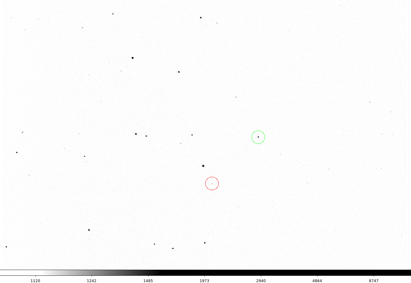
Now pick a second star that is visible on both the POSS2 image and
the VAO image. To get the best WCS, the star should be quite
far from the first star and not be saturated. It's better
not to use the star in the red circle, as it is rather close to BD
+47 3462 which will reduce the accuracy of your measurements of s
and θ.
It is probably best to load both two images into ds9 and view them
simultaneously using Frame/Tile Frame. Make sure that you
see the whole of each image using Zoom/Zoom to Fit Frame.
Find approximate coordinates for the star using ds9 on the POSS2
image and then identify the star using the Query by coordinates
option in Simbad. Find the CCD coordinates of your star
using your python centroiding code.
Now find the angular distance between the two stars. Note that you need to use spherical trigonometry. Write down the equation for the angular distance in terms the RA and DEC of the two stars and record your calculations. You may want to write a python function to calculate angular distances as you will be doing this for several stars below. Now find the distance in pixels between the CCD coordinates of the two stars. Do you need to use spherical trigonometry? Think about the fact that we are using a tangent projection for the coordinate system. Take the ratio of the two values, this is your value for s = angular size of pixels.
Now find the angle between a line drawn from BD +47 3462 to your second star in astronomical coordinates and a line draw due north from BD +47 3462. Also find the angle between a line draw from BD +47 3462 to your second star in CCD coordinates and a line draw towards positive x from BD +47 3462. This is the rotation angle of the image. You might draw a 'ruler' object using ds9, but be careful about how ds9 defines angles, or you might write a bit of code to do this.